installation & adjustment procedures
The adjustment procedures are not difficult if you follow my outline. If you purchased a restored switch from Certified Rebuilders adjustments generally should not be necessary. As these switches are setup & pre-set when they are completed. Due to the gear play within your upper back panel gear box this may necessitate adjustments. There are factory adjustment procedures in the OE repair manuals but I think you'll find my procedures along with pictures and color coding for the Tbird switch & Lincoln switch helpful. To become familiar with the process you may want to print this page and review it before starting.
Please credit "Certified Rebuilders LLC" if you are using, printing, forwarding or reposting this procedure. Good-Luck !
1964-1966 Thunderbird Convertible Upper Back Panel Limit Switch
Step 1 Determine if your switch is an OE Tbird style or Lincoln replacement
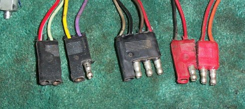
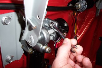
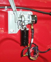
Lincoln Switch will have 2 four wire black connectors and 1 four wire red connector. A total of 12 electrical connections on the switch housing. Notice in the picture below that the red wire connector is cut in half . The half of the red connector with the two male prongs (red/grn wire & org wire) are not used for the Thunderbird. This connector may have been removed or taped back into the wire harness. The black connector with one male contact and three female contacts is also cut in half. The connector half with two female contacts (red/wht wire & green or grn/wht wire) is taped side by side to the red connector with one male and one female contact (black wire & red wire). Check the pictures.
Original Lincoln Switch Wire Connectors
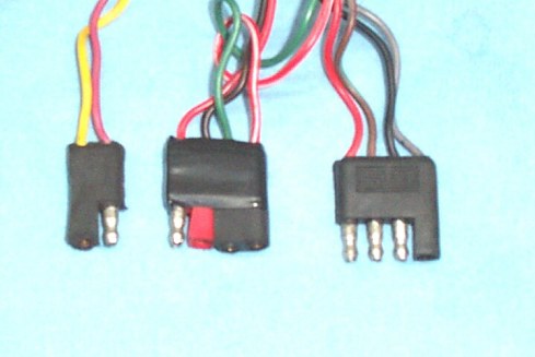
Lincoln Switch Wire Connectors Cut
Lincoln Wire Connectors Taped Together
Ford's Wire Modifications for using the Lincoln switch on a Thunderbird
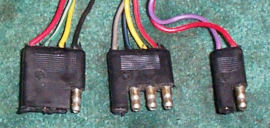
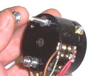
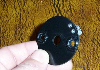
Thunderbird Switch will have 2 four wire connectors and 1 two wire connector. A total of 10 electrical connections on the switch housing
Thunderbird Switch Wire Connectors
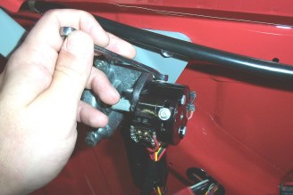
Step 2 Open the rear decklid and extend the flip lid panel to approximately 75% extension. This will enable the removal and or installation of the switch. It's almost impossible to install the switch with the flip lid 100% erected or retracted.
Flip Lid 75% Extended
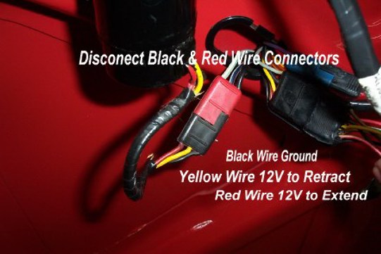
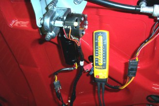
To manually control the rear flip lid, disconnect the black & red flip lid motor wire connector. Supply power and ground as outlined in the picture to extend or retract the flip lid
Flip Lid Motor Wire Connector
Note: wire colors may be reversed..
Flip Lid Motor Black Wire Connector
Black Wire
|
Supply Ground (-)
|
Red Wire
|
Supply Power (+) to Extend
|
Yellow Wire
|
Supply Power (+) to Retract
|
NOTE:.....wire colors may be reversed to extend and or retract......50% of the vehicles were built with reversed color wiring...
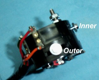
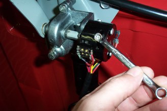
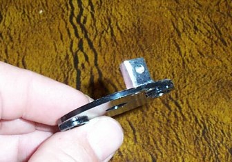
Step 3 Before mounting the switch to the gear box, using a 1/4" wrench, back off the inner and outer bolts on the switch halves (rings) until they're extremely loose. Not falling out but loose enough where you can see that the washer under the bolts can move freely.
Using a 3/8" wrench, remove the two outer star nuts. These are used to mount the switch onto the gear box.
Using the 3/8" wrench, slightly back off the 2 nuts that hold the switch halves (rings) together.
At this point, with the switch in your hands, you should be able to slightly rotate the inner & outer switch halves (rings). We don't want it too loose to the point where the switch halves come apart. The mechanisms inside are under spring tension and will fly apart like a Swiss watch.
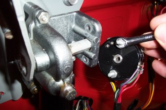
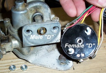
Step 4 Using a flat head screwdriver align the switch to the gear box. It may be necessary to rotate the center spindle in the switch to align the "D" shaped shaft on the arm and the "D" shaped hole on the spindle.
Step 5 Using the 2 star nuts mount the switch to the gear box. Tighten down the 2 star nuts to slightly secure the switch to the gear box, no movement but not totally tightened down to the point where the switch halves will not rotate. We need the switch halves to be able to rotate while it is mounted to gear box. The switch wiring connectors are not to be connected to the vehicles wiring harness
Step 6 A Quick review so far
Step 1
|
Determine your switch type
|
OK
|
Step 2
|
Extend flip lid panel to 75% erect
|
OK
|
Step 3
|
Loosen the inner & outer switch halves (rings)
|
OK
|
Step 4
|
Align the "D" center on the switch to the gear box
|
OK
|
Step 5
|
Mount the switch to the gear box (not too tight)
|
OK
|
FLIP LID MOTOR COLORS MAY BE REVERSED...........
Step 7 First Adjustment
With the switch mounted to the gear box, disconnect the flip lid motor wire black connector from the vehicle wire harness red connector if you had not done so earlier. On the black motor connector, using jumper wires and the table below, fully extend the flip lid to 100% erect.
Flip Lid Motor Black Wire Connector
Black Wire
|
Supply Ground (-)
|
Red Wire
|
Supply Power (+) to Extend
|
Yellow Wire
|
Supply Power (+) to Retract
|
Step 8 Find the following wire color combinations on one of the switch wiring connectors. The wire color combinations are side by side in the same connector. Check the pictures of the connectors from the beginning.
Thunderbird Switch
|
Black Connector
|
gray wire & black with blue strip wire
|
Lincoln Switch
|
Black Connector
|
gray wire & black with blue strip wire
|
Step 9 Using a self powered test light, continuity tester, or ohmmeter connect to the two wire connectors as outlined in the chart.
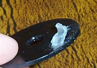
Step 9 With the flip lid fully extended rotate the outer switch halve just until the point where your tester goes from continuity to no continuity. While holding the switch half in this position, using your 1/4" wrench tighten down the outer switch half adjustment bolt. If your switch has the original plastic thread housings do not over tighten the bolts. Over tightening the bolts will tear and crack the plastic thread housings
If your switch has the new aluminum adjustment blocks this will not be an issue. These aluminum blocks will not strip out or crack.
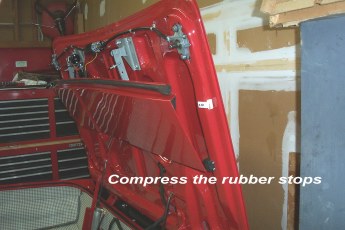
Step 10 With the first adjustment complete, retract the flip lid using you jumper wires and the flip lid motor wire color chart. Retract the flip lid to the point where the flip lid compresses the rubber bumpers on the underside of the deck lid. The flip lid should compress the rubbers by 30 to 60 percent of their normal shape when the flip lid is not retracted.
Step 11 Again, with the switch wiring harness disconnected from the vehicle wiring harness, find the following wire combinations on one of the switch wiring connectors. The wire color combinations are side by side in the same connector. Use the table below and the wiring pictures from the step 1 if needed.
Thunderbird Switch
|
Black Connector
|
Green with White Stripe Wire & Red Wire
|
Lincoln Switch
|
Black Connector (half)
|
Red with White Stripe Wire & Green with White Stripe
|
Using your self powered test light, ohmmeter, or continuity tester connect to these 2 wires on the switch wiring connector. Rotate in the inner switch halve (closest to the gear box) just until the point where the test light goes from continuity to no continuity. Hold the inner switch halve in this position and tighten down the inner adjustment bolt to hold the switch halve from moving.
Step 12 With the adjustments complete, extend the flip lid panel to approximately 75% extended.
Flip Lid Motor Black Wire Connector
Black Wire
|
Supply Ground (-)
|
Red Wire
|
Supply Power (+) to Extend
|
Yellow Wire
|
Supply Power (+) to Retract
|
Remove the 2 star nuts that secure the switch to the gear box and remove the switch.
With the 2 inner nuts now visible, securely tighten down the 2 switch halve nuts that hold the switch together.
Reinstall the switch back onto the gear box using the 2 star nuts and securely tighten the switch.
Reconnect the black flip lid motor wire connector to the vehicle's red wire connector. Connect the upper back panel limit switch wire connectors to the vehicle's wire harness connector
That will complete the adjustment procedures. Congratulations !!!!!!!!!